
H7 Bores, Reaming vs Drilling, and Bolt-Circle True Position — A Buyer’s Guide
Holes are the most common CNC feature—and the #1 source of tolerance-related rejects. This guide explains what H7 actually means, when to choose reaming vs drilling vs boring, how to control true position on bolt circles, and how to cut cost without compromising fit.
Precision H7–H8, CMM Reports
Reamed/bored bores, GD&T-based inspection, PPAP/ISIR on request.
Scale Through 20k+ Suppliers
Prototype to production with managed QC, finish, and logistics.
Cost-Down Without Risk
Specify tight fits only where functional — we’ll guide the callouts.
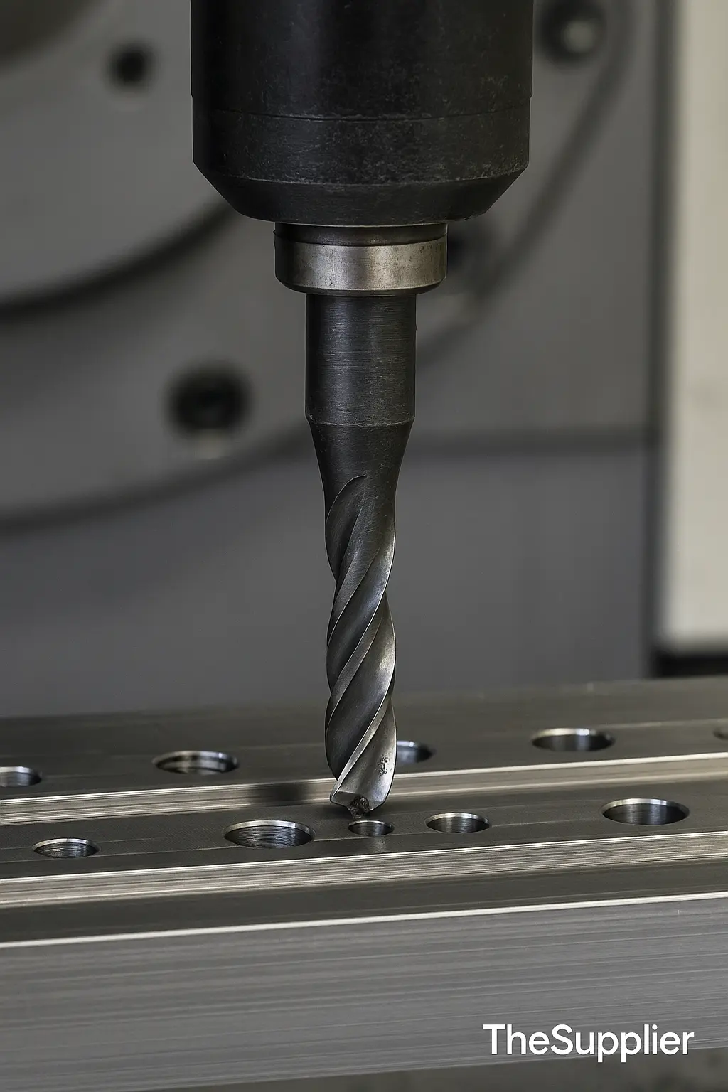
What Is CNC Drilling?
CNC drilling is the process of creating cylindrical holes using a rotating twist drill under precise, computer-controlled feeds and speeds. It’s the fastest way to generate holes, but raw drilled holes typically have wider tolerances and rougher surface finishes than reamed or bored holes.
Standard drilling: general-purpose holes; best for clearance features and pre-ream sizing.
Peck drilling: intermittent retractions to break chips and improve straightness in deeper holes.
Deep-hole / gun drilling: extreme depth-to-diameter ratios with through-tool coolant for chip evacuation.
| Method | Typical Accuracy | Surface Finish (Ra) | When to Use |
|---|---|---|---|
| Drilling | ±0.10–0.20 mm | 3.2–6.3 μm | Clearance holes, pre-size for reaming/boring |
| Reaming | ±0.01–0.05 mm (H7/H8) | ≤1.6–0.8 μm | Precision bores with smooth finish for dowels/bearings |
| Boring | ±0.005–0.02 mm | ≤0.8 μm | Tight bores, concentricity to datums, adjustable size |
| Milling a hole | ±0.02–0.10 mm | 1.6–3.2 μm | Non-circular or offset features, pockets with holes |
Related reading: CNC Machining Tolerances Explained, CNC Machining Services, Upload Drawing & Get Managed Quote.
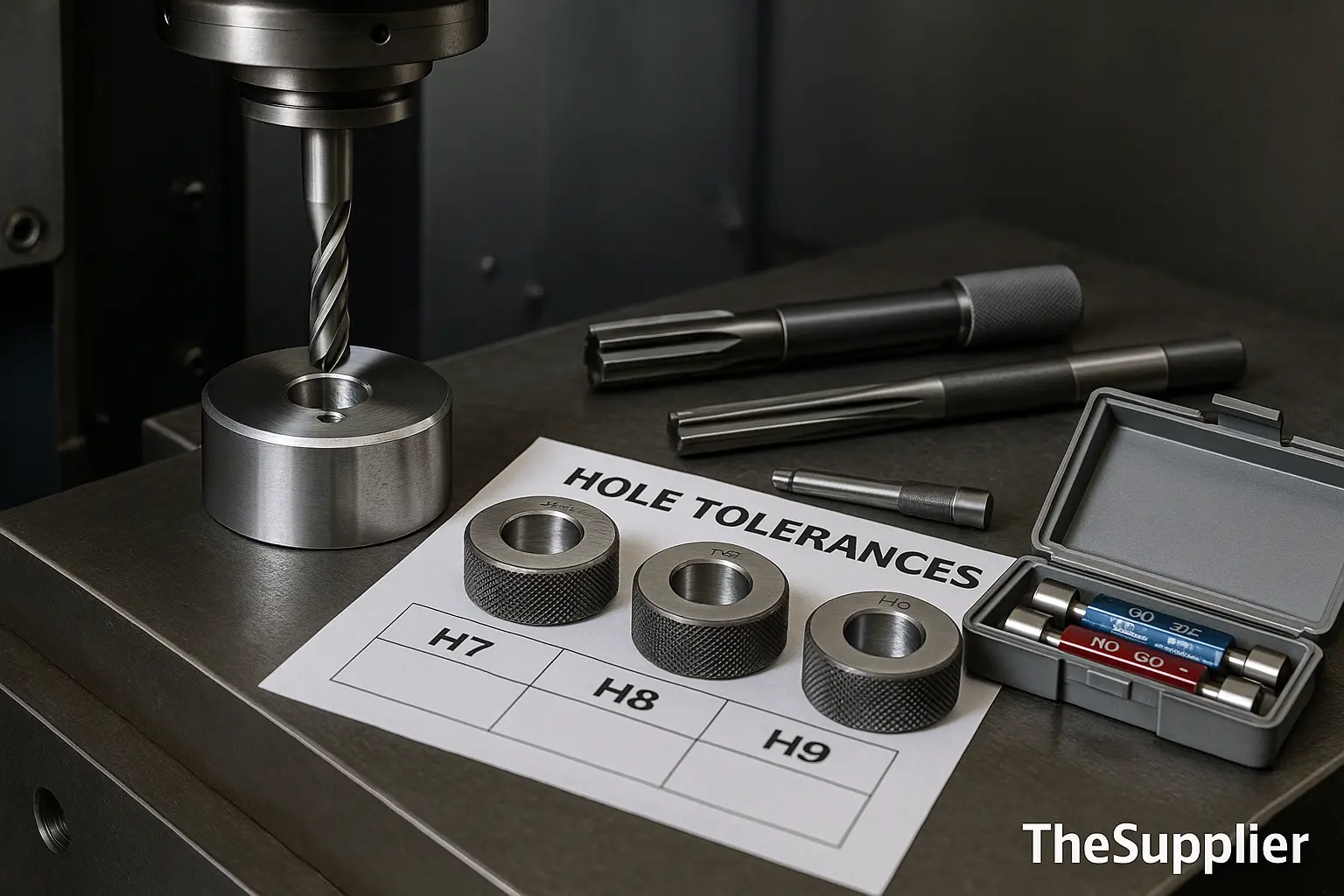
Hole Tolerances Explained: H7, H8, H9 (ISO 286 Fits)
ISO hole basis tolerances like H7, H8, H9 define how much a hole’s diameter may deviate from its nominal size. In the “H” hole system, the lower deviation is zero (no undersize), and the tolerance is a positive band above nominal. This is why drawings often show values like Ø20 H7 = +0 / +0.021 mm.
When to choose
- H9/H11: clearance holes, fasteners, general purpose where location is not critical.
- H8: functional clearance where improved guidance is needed (pins, simple bushings).
- H7: precision sliding fits, dowel/bearing bores, seal interfaces, alignment-critical parts.
Remember: the same H7 code yields different micrometer values depending on the diameter range. Larger diameters have a wider tolerance band.
Related reading: CNC Machining Tolerances Explained • Need an H7 bore held and certified? Upload your drawing.
| Nominal Ø | H7 (upper tol) | H8 (upper tol) | H9 (upper tol) | Example Callout |
|---|---|---|---|---|
| Ø10 mm | +0.015 mm | +0.022 mm | +0.036 mm | Ø10 H7 ⇒ 10.000 / 10.015 |
| Ø20 mm | +0.021 mm | +0.033 mm | +0.052 mm | Ø20 H7 ⇒ 20.000 / 20.021 |
| Ø30 mm | +0.025 mm | +0.039 mm | +0.062 mm | Ø30 H7 ⇒ 30.000 / 30.025 |
| Ø50 mm | +0.035 mm | +0.054 mm | +0.087 mm | Ø50 H7 ⇒ 50.000 / 50.035 |
Values are representative examples used commonly by buyers; always confirm against your governing standard/datasheet.
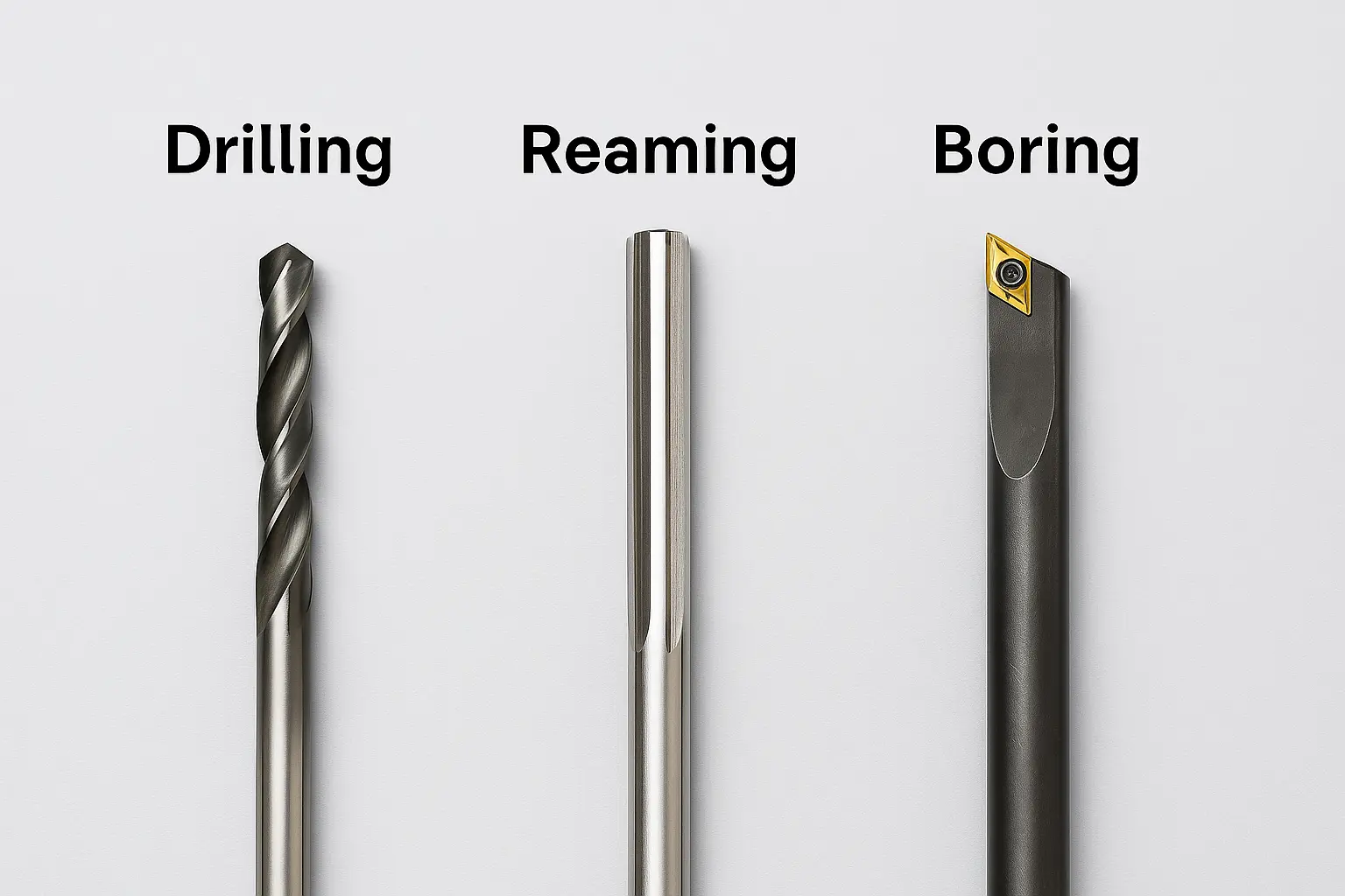
Reaming vs Drilling vs Boring — Which One Should You Specify?
Choose the method based on required accuracy, surface finish, concentricity to datums, and cost. In most production drawings, drilling creates the pilot; reaming or boring achieves the final tolerance (e.g., H7).
Drilling (Pilot)
- Accuracy: typically ±0.10–0.20 mm
- Finish: Ra 3.2–6.3 µm
- Use for: clearance holes, pre-size for ream/boring, tapping pre-drill
- Tip: use peck drilling & through-coolant for deep holes
Related: What is CNC Drilling?
Reaming (Precision Bore)
- Accuracy: ±0.01–0.05 mm (H7/H8 common)
- Finish: ≤1.6–0.8 µm
- Use for: dowel/bearing bores, sliding fits, seal interfaces
- Tip: specify reaming wherever you call H7 on drawings
Learn: Tolerances Guide
Boring (Adjustable & Concentric)
- Accuracy: ±0.005–0.02 mm
- Finish: ≤0.8 µm
- Use for: tight bores, coaxiality, fine adjustment of size
- Tip: boring is slower but ideal for critical datum alignment
Need help? Upload your drawing for DFM
| Method | Typical Tolerance | Surface Finish (Ra) | Concentricity to Datums | Cycle Time / Cost | Common Use |
|---|---|---|---|---|---|
| Drilling | ±0.10–0.20 mm | 3.2–6.3 µm | Low–Medium | Very Low | Clearance, pilot for ream/boring |
| Reaming | ±0.01–0.05 mm (H7/H8) | ≤1.6–0.8 µm | Medium | Low–Medium | Dowels/bearings, sealing bores |
| Boring | ±0.005–0.02 mm | ≤0.8 µm | High | Medium–High | Critical fits & datum alignment |
Rule of thumb: if your drawing calls out H7, a drilled-only hole will likely fail. Use reaming or boring depending on concentricity needs.
Stainless & titanium increase drill wander and heat; use carbide, through-coolant, and proper pilot sizes. Aluminum/brass ream well but can bell-mouth if feed is too high.
Call tight tolerances only where function requires. For mixed stacks, use GD&T true position for bolt circles and define datums to avoid tolerance stack-up.
Related: H7/H8/H9 tolerance examples, Turning Components, Milling Surface Finish, Share your drawing for a managed quote.
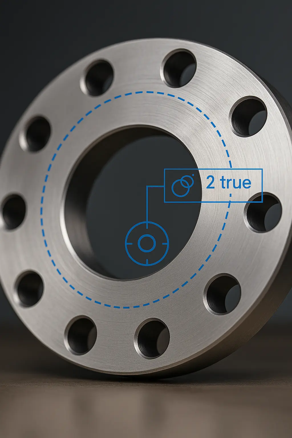
Bolt-Circle & True Position — Get the Pattern Right
Linear ± tolerances on individual holes often fail to guarantee a bolt-circle matches its mating part. GD&T true position solves this by defining a cylindrical tolerance zone around each intended hole center, referenced to datums on your part.
How True Position Works
- Datums: Choose primary/secondary datums (e.g., flange face A, center bore B) so hole locations are measured relative to function.
- Tolerance: Specify a positional tolerance (e.g., ⌀0.10) that forms a zone where the actual hole axis must lie.
- MMC Bonus: Add MMC (Maximum Material Condition) to gain extra positional tolerance when the hole is larger than its minimum size.
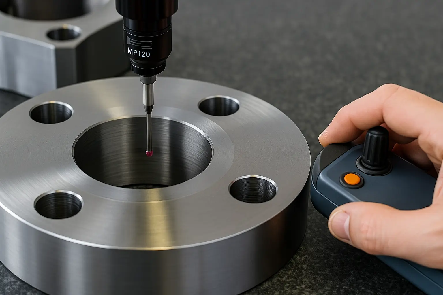
- Validation: Use CMM or a functional gauge to verify; avoid relying on calipers alone for pattern accuracy.
Example: 6X Ø10 H9 Ⓣ ⌀0.10 M A|B means 6 holes of Ø10 with H9 size, true position ⌀0.10 at MMC relative to datums A and B.
Related: Reaming vs Drilling vs Boring • H7/H8/H9 tolerance examples • Upload your drawing.
For flanges, face A and center bore B are typical. Avoid using outer profile as a primary datum when the function is face-to-face sealing and coaxiality.
Pair the hole size (e.g., Ø10 H9) with the true position frame so inspectors can apply bonus tolerance when the hole is on the larger side.
For production, a functional gauge catches issues faster than 100% CMM. Reserve detailed CMM for first articles and periodic audits (AQL).
Common Mistakes to Avoid
- Using only ± linear dimensions for a bolt circle — patterns end up rotated or off-center.
- Omitting datums — inspectors reference different features and get inconsistent results.
- Calling H7 on holes intended for fasteners — use H9/H11 unless a fit requires tighter control.
- Skipping pilot + ream on tight patterns — drilled-only holes wander and stack errors.
What is true position tolerance?
It defines a cylindrical zone in which the actual hole axis must lie relative to specified datums. It controls location, not size.
When should I add MMC to true position?
When function allows more location error as the hole grows from minimum size. MMC provides bonus tolerance and improves manufacturability.
How do I select datums for a flange?
Use the sealing face as primary (A) and the center bore as secondary (B). This mirrors real assembly constraints and yields repeatable inspection.
Can drilling alone hold a tight bolt-circle?
Rarely. Use a pilot + ream strategy and define true position to keep the pattern accurate to the mating part.
Need help applying GD&T? Send your drawing — we’ll add datum schemes and inspection plans that match function and cost.
Materials, Tooling & Process Effects
Material choice, tool geometry, and chip evacuation decide whether a hole hits its tolerance and finish—especially for H7/H8 bores. Use the guidance below to avoid drill wander, bell-mouthing, and heat-induced shrink/growth.
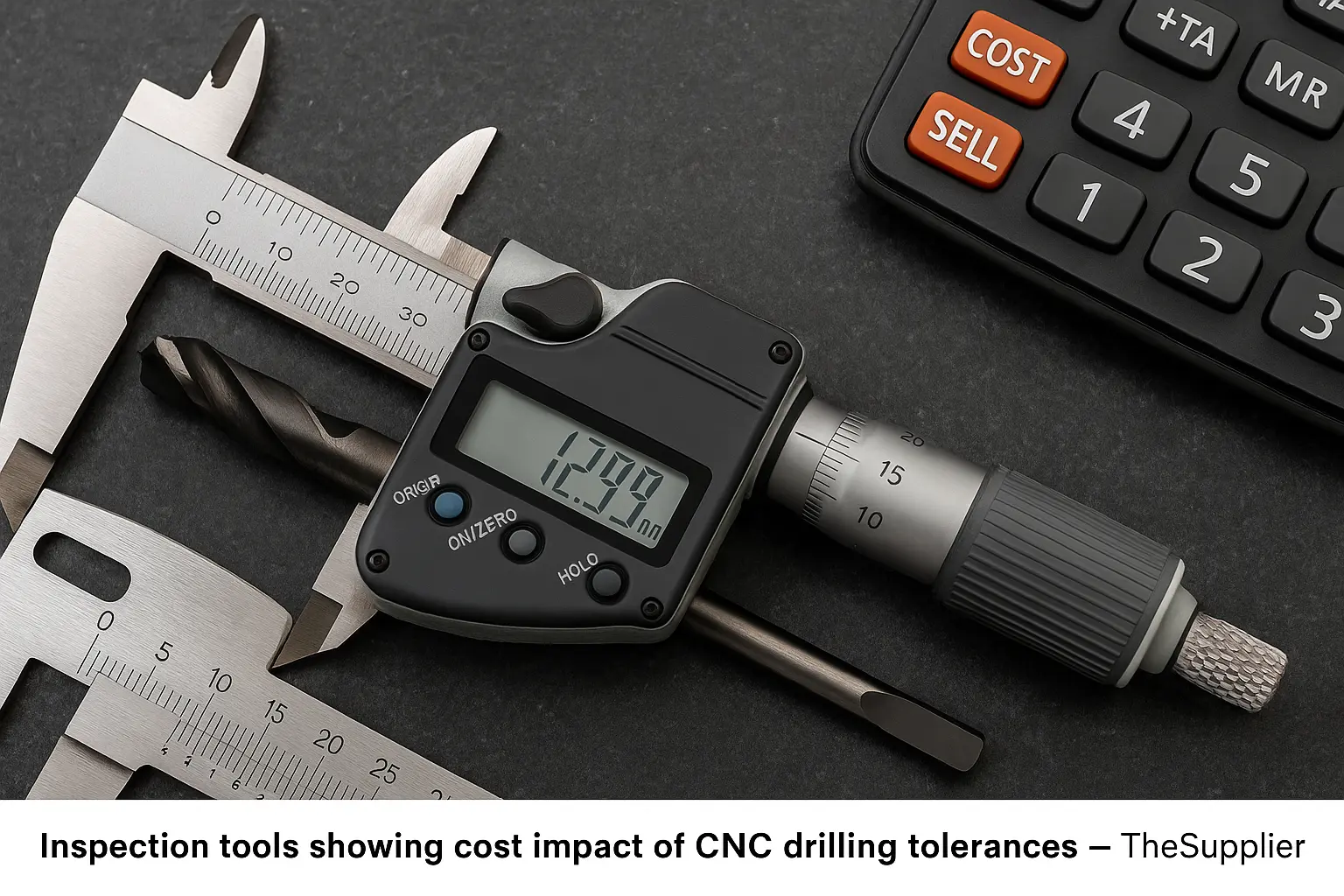
Cost Drivers & Buyer Tips
Tight tolerances and finishing add cost — but only when used indiscriminately. Knowing what actually drives cost helps you specify smarter and avoid hidden price escalations.
Key Cost Drivers
| Driver | Impact | Buyer Consideration |
|---|---|---|
| Reaming / boring operations | +1 extra cycle, special tools | Specify only where functional fit (H7/H8) is needed |
| Tool wear in hard alloys | Frequent tool change, slower feed | Expect premium for SS/Ti parts; ask supplier about tool life strategy |
| Inspection requirements | CMM programming & cycle time | Request PPAP/ISIR only on critical parts, not every batch |
| Tight bolt-circle true position | Higher scrap risk if uncontrolled | Add MMC to tolerance frames to reduce scrap & cost |
| Plating / anodizing after drilling | Size change due to coating thickness | Clarify if tolerance is before or after finish |
For practical tolerance strategies, revisit H7/H8/H9 examples or true position notes. You can also see our CNC Tolerance Guide.
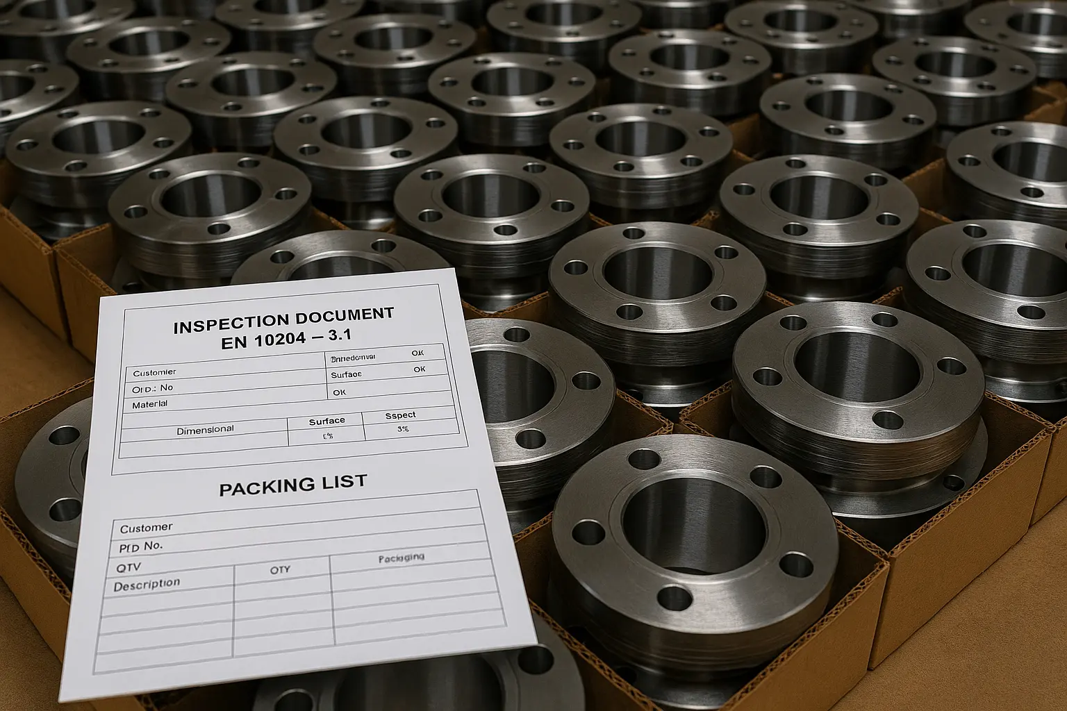
Case Study — Flange with H7 Bores & True-Position Bolt Circle
A Gulf-region pump OEM faced recurring assembly failures from misaligned bolt holes and rough bores. TheSupplier stabilized the spec, introduced reaming and positional GD&T, and delivered export-ready lots with full inspection.
Buyer’s Checklist — CNC Drilling & Hole Tolerances
Use this quick list before you release drawings or an RFQ. It keeps cost predictable and reduces rejects.
Hole size & fit: call out the nominal Ø with the required ISO fit (e.g., Ø20 H7, Ø10 H9).
Method: specify pilot + ream (H7/H8) or fine boring when concentricity to datums is critical.
Bolt-circle location: use true position with datums (e.g., Ⓣ ⌀0.10 MMC A|B) instead of linear ± dimensions.
Reamer allowance: leave 2–4% of Ø as stock for reaming; define pilot size on drawing or process sheet.
Finish requirement: state roughness if functional (e.g., Ra ≤0.8 μm for seals/bearings). Avoid specifying where not needed.
Coating & size basis: clarify if tolerances are before or after plating/anodize/passivation.
Inspection plan: request GO/NO-GO plugs for H7/H8 and positional checks via CMM on first-articles + AQL sampling.
Datums: define primary (e.g., sealing face A) and secondary (e.g., center bore B) to match assembly function.
Quantities & releases: stabilize pricing with blanket POs and scheduled releases for recurring demand.
Attachments: include drawing (PDF + DXF/STEP), tolerance table references, and any prior deviations/waivers.
Need a second set of eyes? Share your print and we’ll mark up GD&T and inspection once, so every release is repeatable. See: CNC Tolerance Guide · CNC Machining Services · Upload Drawing
Frequently Asked Questions — CNC Drilling & Hole Tolerances
What does H7 tolerance mean in holes?
It’s an ISO hole-basis fit where the lower deviation is zero and the upper limit depends on diameter. Example: Ø20 H7 = 20.000 / 20.021 mm.
What’s the difference between drilled and reamed holes?
Drilling is fast but only ±0.1–0.2 mm accurate. Reaming improves roundness, size control (±0.01–0.05 mm), and surface finish (≤1.6 μm).
Can boring replace reaming?
Boring achieves even tighter tolerances and concentricity but at higher cycle time. Reaming is more cost-effective for most H7 bores.
What is true position in GD&T?
It defines a cylindrical tolerance zone around a hole’s true center relative to datums. Ensures bolt-circle patterns align without relying on ± linear dimensions.
Should I specify H7 on all holes?
No. Use H9/H11 for clearance fastener holes and reserve H7/H8 for functional fits like dowels, bearings, and seals.
How do coatings affect hole size?
Plating or anodizing reduces clearance by coating thickness. Clarify if tolerance is before or after finish to avoid mismatched parts.
What’s the inspection method for H7 bores?
GO/NO-GO plug gauges or CMM with datum references. For production lots, AQL sampling is typical; for FAIs, 100% CMM checks.
Does material choice affect cost for H7 holes?
Yes. SS and Ti wear drills faster and require carbide + coolant. Expect higher cost vs. aluminum or brass which ream easily.
How to control hole straightness in deep drilling?
Use peck cycles, through-coolant drills, or gun drilling for L/D > 10:1. Always follow with reaming if a precision bore is required.
Do you provide CMM/inspection reports?
Yes. TheSupplier delivers PPAP/ISIR, CMM data, and gauge certifications for H7/H8 bores and positional tolerances on request.

