
Over-tight tolerances multiply cost; under-tight tolerances multiply risk. This guide shows how to set CNC tolerances that protect function, speed up delivery, and keep your price lean.
What you’ll discover in 7 minutes
- Which tolerances drive cost and which do not (with price multipliers).
- Recommended default CNC tolerances for milling, turning, holes & threads.
- How surface finish, plating, and anodizing change your final dimensions.
- ISO fits (H7/g6, H7/p6) decoded for real-world shafts & bores.
- Tolerance 101 — the 3 buckets buyers control
- The cost curve — what tighter really costs
- Recommended defaults for common features
- Fits that work — H7/g6 & friends
- Finish & plating effects (Ra, anodize, zinc)
- GD&T you should (and shouldn’t) specify
- Inspectability & proof before shipment
- Buyer checklist + free drawing review
1) Tolerance 101 — the three buckets buyers control
All dimensional control ultimately lands in one (or more) of these buckets. Understanding them is the fastest way to set practical CNC tolerances without overpaying.
① Size tolerance (±)
The classic limit like Ø10.00 ±0.05. Decide via functional need, not habit. Every notch tighter increases machine time, scrap risk, and inspection cost.
② Geometric control (GD&T)
Controls shape & relation without choking every size: flatness, perpendicularity, true position, runout. Smart GD&T can relax size while protecting function.
Best for assemblies CMM-friendly③ Surface & edge quality
Roughness (Ra), burrs, chamfers & radii. Finish choices change friction, sealing, fit and even final dimensions after plating/anodize.
Finish affects size See §5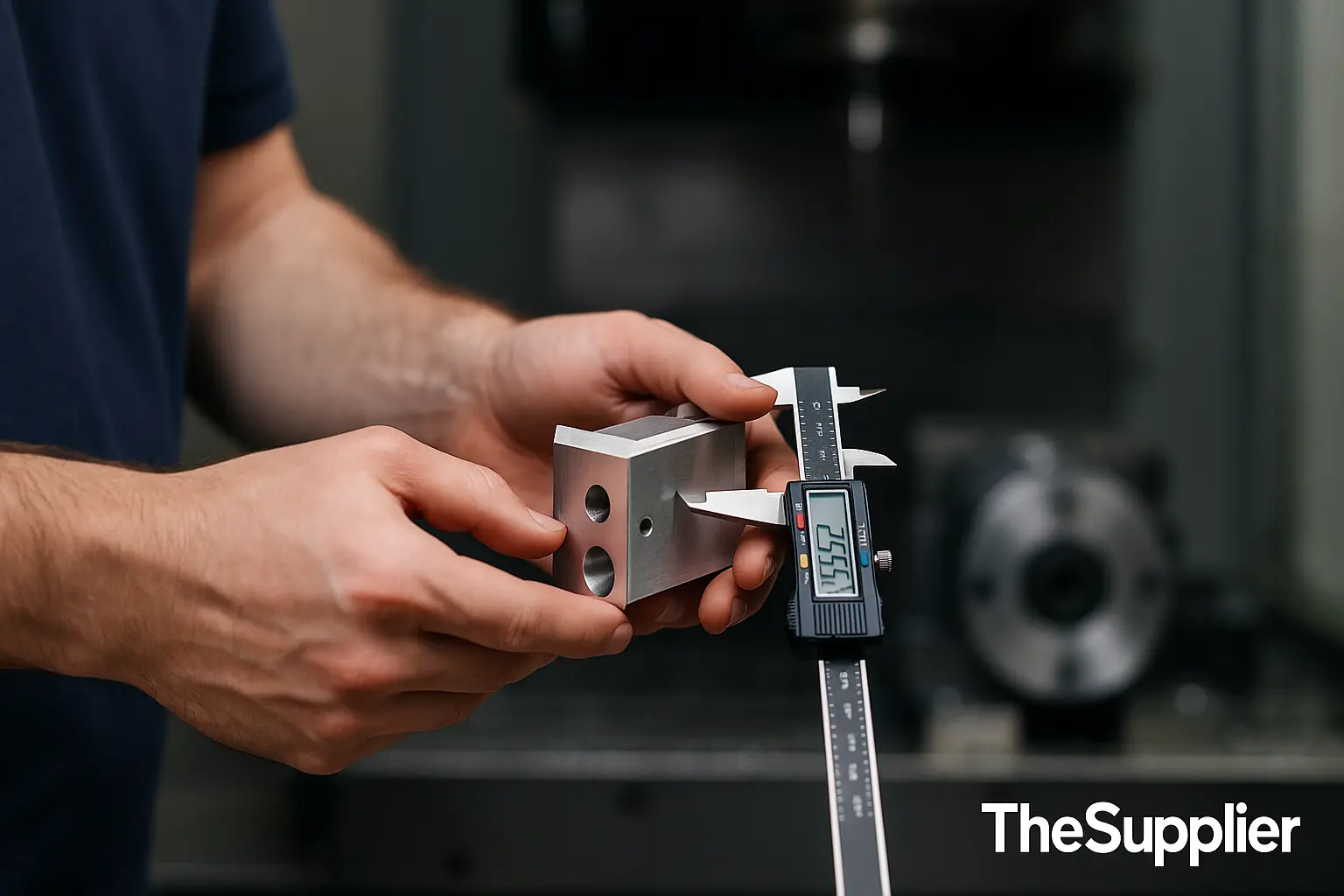
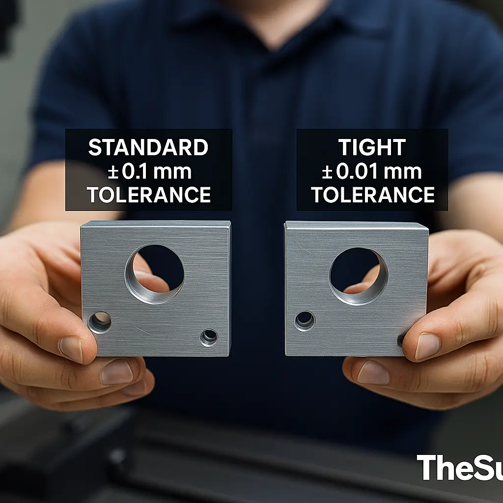
2) The cost curve — what “tighter” really costs
CNC tolerances follow a predictable cost curve. Past a point, you pay a premium for setup time, slower feeds, tool wear, multiple ops, climate control and high-touch inspection.
| Tolerance band (mm) | Typical use | Process notes | Price impact* |
|---|---|---|---|
| ±0.20 to ±0.10 | General features, brackets, covers | 1 pass finish; standard QC | ×1.00 (baseline) |
| ±0.05 | Locating faces, medium fits | Finish pass + controlled tool | ×1.2–1.4 |
| ±0.02 | Precision bores/shafts pre-fit | Multiple ops, stable temp | ×1.5–2.0 |
| ±0.01 | High-accuracy metrology mating | Fine boring/ream; CMM proof | ×2.0–3.0 |
| ±0.005 and below | Tooling, gauges, optics | Climate control, lapping | ×3.0–5.0+ |
*Rule-of-thumb multipliers for guidance only; actual pricing varies by geometry, material, lot size, tool reach, and inspection plan.
Tip: Protect function with GD&T on the few features that matter and keep general size at ±0.10 mm. That single decision often cuts total cost 20–40% on complex parts without changing end performance.
3) Recommended defaults for common features
Use these buyer-friendly defaults when your drawing doesn’t specify otherwise. They’re proven across our 20,000+ supplier network for reliable, economical CNC tolerances.
Faces & profiles (milling)
- Linear dims: ±0.10 mm (general), ±0.05 mm (locators).
- Flatness: 0.05 mm/100 mm unless functional need says tighter.
- Perpendicularity: 0.05 mm/100 mm for mating faces.
Shafts & bores (turning)
- Shaft Ø: ±0.02–0.05 mm pre-fit; use ISO fits for assemblies.
- Bore Ø: ream to H7 if you need consistent clearance.
- Runout: 0.03 mm TIR for bearing seats (typical).
Holes & threads
- Drilled hole: H12–H13 equivalent; ream for tighter.
- Positional tol (true position): Ø0.10–0.25 mm @ MMC on bolt patterns.
- Threads: 6H (metric) / 2B (inch) female; 6g / 2A male by default.
4) Fits that work — H7/g6, H7/p6 & how to use them
Instead of guessing a random ± value, choose a standard fit pair. It communicates both CNC tolerances and intent clearly to any shop worldwide.
| Application | Fit | What you get | Typical outcome |
|---|---|---|---|
| Free sliding & easy assembly | H7/g6 | Small positive clearance | Parts slide, no shake |
| Location/transition | H7/k6 | Zero to slight interference | Light press possible |
| Permanent press fit | H7/p6 | Interference | Strong retention |
Example callout: Ø20 H7 bore + Ø20 g6 shaft. You’ve just defined the clearance range without micromanaging ± size on each feature.
5) Finish & plating effects (Ra, anodize, zinc) that shift size
Surface finish and coatings can reduce clearances or push features out of spec if you don’t account for thickness & chemistry.
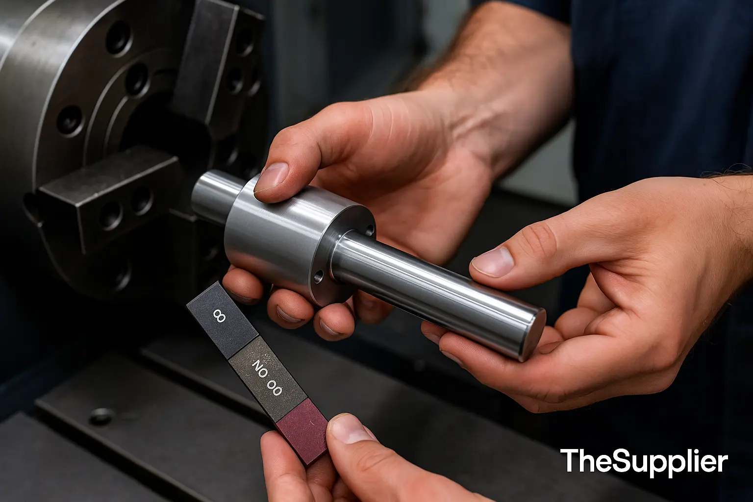
Roughness (Ra)
General machined Ra 1.6–3.2 μm is typical. Bearing seats may need ≤0.8 μm Ra. Chasing Ra too low adds passes/tooling time; only tighten where friction or sealing needs it.
Anodizing (Al)
Type II adds roughly 5–25 μm thickness (≈ half grows inward, half outward). Critical bores should be masked or finished after anodize/honed to size.
Zinc/ENP/Plating
Typical build 5–20 μm. Threads and slip fits can seize if not masked or toleranced for post-plate condition.
Call out whether tolerances apply before or after coating. We’ll advise the most economical route.
6) GD&T you should (and shouldn’t) specify
Use GD&T where it protects function; avoid blanket geometric callouts across every feature.
✅ Smart to add
- Flatness on sealing faces.
- Perpendicularity between bearing bores & mounting faces.
- True position on bolt circles/dowel holes with MMC.
- Runout on rotating diameters.
⚠️ Use sparingly
- Profile on every surface (hard to inspect, costly).
- Ultra-tight parallelism/flatness with no functional driver.
Datum strategy
Pick functional datums: a primary mounting face (A), a locating edge (B), and a hole/slot (C). Consistent datums reduce variation through the whole stack-up.
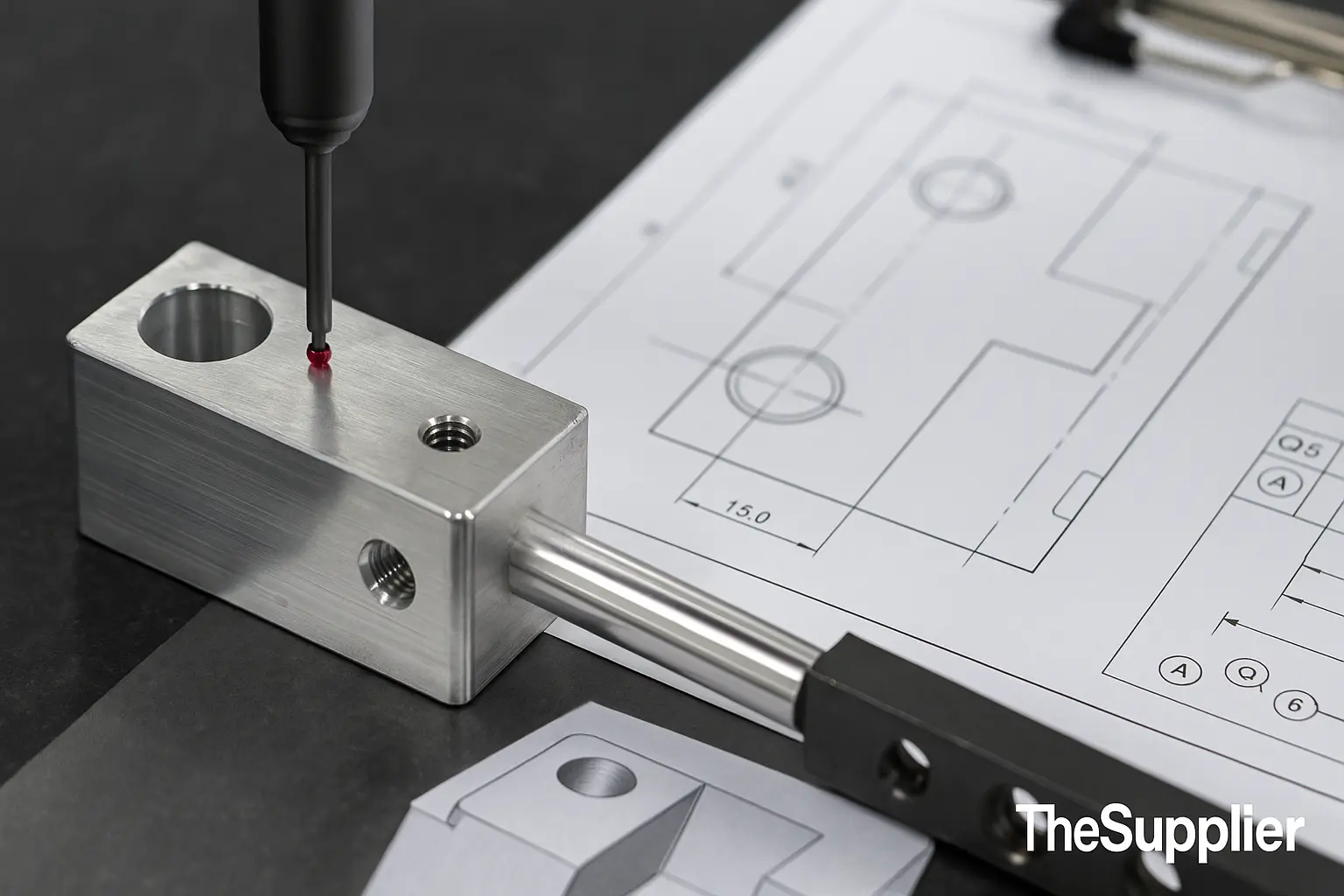
7) Inspectability & proof before shipment
A tolerance is only as good as the way you verify it. Your quote should define the inspection level required.
| Level | When to choose | What you receive |
|---|---|---|
| Standard QC | General parts, ±0.10 mm | Spot checks + basic report |
| Critical features list | Few key dims matter | 100% check on named features |
| Full CMM report | GD&T, precision bores/shafts | Ballooned drawing + CMM data |
| Gauge/Fixture proof | Production assemblies | Go/No-Go data, runout plots |
8) Buyer checklist — set the right CNC tolerances in minutes
Use this five-point checklist to lock performance and save cost on your next RFQ.
1) Mark criticals
Circle the 3–5 features that actually control function. Put GD&T on those features; keep general ± at ±0.10 mm.
2) Choose fits
Use H7/g6 for sliding fits, H7/p6 for press. Avoid random ± on shafts/bores.
3) Declare finish
State Ra and coating condition (before/after plating). Mask criticals or hone after coat if needed.
4) Define inspection
Standard QC, critical features, or CMM? Ask us for the most economical plan that still proves function.
5) Add context
Note mating parts, loads, temperature and life. A bit of context lets us suggest cheaper paths.
Free tolerance review in 24h. Upload your drawing — we’ll mark suggested CNC tolerances, fits, and inspection levels to hit your function at the lowest cost.
CNC Tolerances — Frequently Asked Questions
What are standard CNC machining tolerances if I don’t specify them?
Our default is ±0.10 mm on linear dimensions, ±0.05 mm on key locators, standard drilled holes, threads to 6H/6g (metric) or 2B/2A (inch), and general Ra 1.6–3.2 μm unless noted. Tell us if a feature is critical and we’ll tighten only where it matters.
How does plating or anodizing affect my tolerances?
Coatings add thickness (often 5–25 μm) and can reduce clearances or close threads. Call out whether tolerances apply before or after coating. We can mask critical features or finish-machine/hone post-coat.
Should I use GD&T or just tighter ± on everything?
Use GD&T on functional relationships (flatness, perpendicularity, true position) and keep general ± relaxed. This approach protects assemblies and typically cuts cost 20–40% vs. globally tight ±.
What inspection report will I receive?
Standard jobs include spot checks; critical jobs include 100% check on named features; tight GD&T or fit parts can include full CMM with ballooned drawings on request.
Can you help choose ISO fits (H7/g6 etc.) for my drawing?
Yes. Share your shaft/bore function and we’ll recommend a proven fit pair (e.g., H7/g6 sliding, H7/p6 press) with practical tolerances and suggested inspection.
This article is part of TheSupplier’s buyer education series on precision manufacturing and CNC tolerances.

