CNC Milling Surface Finish Guide — Ra Values, Charts & Coating Impact
Understand, specify, and inspect CNC milling surface finish with confidence. This guide explains Ra (µm/µin) conversion, practical finish ranges, the real effects of anodizing and plating, and buyer tips to achieve premium results without overspending.
- A plain-English definition of Ra with a quick µm ⇄ µin converter.
- A buyer-safe surface finish chart for milling, grinding, bead-blast, and polishing.
- Clear guidance on how feeds/speeds, tools, rigidity, and materials change finish.
- How anodizing, electroless nickel (EN), and zinc plating affect roughness and appearance.
- A practical drawing checklist and inspection tips to avoid rework.
Why CNC milling surface finish matters
Finish isn’t just “how it looks.” The right roughness supports fit, sealing, wear life, corrosion resistance, and perceived quality. Getting it right early prevents avoidable cost and delays at PPAP, FAI, or incoming inspection.
Fit & friction
Sliding interfaces (guides, dovetails, linear bushings) last longer and run cooler when roughness peaks are controlled. Excessive Ra increases friction and wear, which can trigger noise and stick–slip during assembly.
Sealing & leakage
Gasketed surfaces usually perform best with Ra ≤ 1.6 µm and controlled lay. Too rough traps micro-channels for leaks; ultra-smooth can reduce gasket bite. The sweet spot protects both seal integrity and cost.
Coating performance
Coatings reflect the underlying texture. Light texture can aid adhesion, but tool marks telegraph through anodizing. A short finishing pass or bead-blast before coating often delivers the clean, uniform aesthetic buyers expect.
Brand & cosmetics
A consistent, repeatable finish is part of your product language. Even when Ra is moderate, a uniform matte appearance can look premium and photograph well for marketing and datasheets.
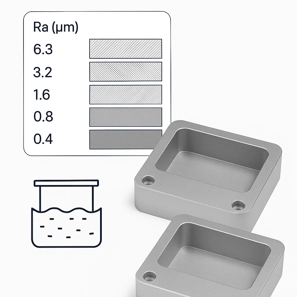
Ra explained (Roughness Average) + quick converter
Ra is the arithmetic average of absolute deviations from the mean line of a surface profile measured over a defined cutoff length. It’s the most common roughness parameter on machining drawings, easily measured by contact profilometers and widely understood by quality teams.
When to specify Ra vs a visual note
Use Ra where function depends on contact (sealing, sliding, bearing surfaces). Use a visual note when appearance matters more than the absolute number (e.g., “Uniform bead-blast + clear anodize on external faces”). For most parts, combine both: Ra callout only on critical faces; visual texture on the rest.
Related: CNC Machining Tolerances — Explained
Quick µm ⇄ µin converter
1 µm = 39.37 µin
Example: Ra 1.60 µm max on faces A/B
Need help choosing where to apply Ra vs visual? See CNC Machining Services.
Typical surface finish ranges by process
These ranges reflect realistic outcomes in aluminum and steel with good tooling and setups. Treat them as buyer-friendly guides; the exact result depends on toolpath, rigidity, material, and lubrication.
| Process | Typical Ra (µm) | Typical Ra (µin) | Where it’s used |
|---|---|---|---|
| Milling — general | 3.2 – 6.3 | 125 – 250 | Internal pockets, non-cosmetic faces |
| Milling — finishing pass | 1.6 – 3.2 | 63 – 125 | Visible faces, edges that will be coated |
| High-finish milling | 0.8 – 1.6 | 32 – 63 | Sealing faces, sliding surfaces, premium cosmetics |
| Grinding | 0.1 – 0.4 | 4 – 16 | Hardened steels, precision datum faces, bearing seats |
| Polishing (mechanical) | 0.05 – 0.1 | 2 – 4 | Mirror visuals, optics, decorative features |
| Bead-blast (visual) | ~ 1.6 – 6.3 | ~ 63 – 250 | Uniform matte to hide tooling and unify appearance |
Unsure which band your part will land in? Upload RFQ.
What actually affects surface finish on milled parts
Tooling condition
Fresh cutters shear cleanly; worn edges plough and smear, increasing Ra and burrs. Coatings (TiB₂ on aluminum, TiAlN on steels) reduce built-up edge that ruins texture.
Feeds, speeds & step-over
Lower feed per tooth, higher RPM (within limits), and small step-overs reduce scallop height. Finish passes often use step-over at 3–8% of tool diameter.
Toolpath strategy
Constant-scallop or morph finishing yields uniform lay on 3D surfaces. Climb milling usually gives better surface than conventional on most materials.
Rigidity & vibration
Long stick-out, flexible fixtures, and aggressive entry moves cause chatter marks. Shorten overhang, increase support, and tune engagement to kill waviness.
Coolant / lubrication
Directed flood or MQL reduces welding on the edge. In aluminum, a fine finishing pass with mist often outperforms dry cutting for Ra and burr control.
Edge prep & deburr
Sharp corners look rough once coated and are unsafe in assembly. Call out break all sharp edges or a controlled chamfer (0.2–0.5 mm).
Recommended finish targets by material
Aluminum 6061/6082: finishing pass typically hits Ra 1.6–3.2 µm. For visible faces before anodizing, target ≤ 1.6 µm to avoid telegraphing.
Aluminum 7075: also finishes well; similar targets to 6061.
Stainless (304/316): gummy; finishing at Ra 1.6–3.2 µm is realistic without grinding.
Carbon Steel (1018/1045): stable finishing; 1.6–3.2 µm typical, grinding to 0.1–0.4 µm when needed.
Plastics (POM/ABS/PC): Tooling marks can be visible even with low Ra; use razor-sharp cutters and light step-over.
Explore our capability stack: All Capabilities.
Anodizing, plating & bead-blast — what they really do to finish
Finishes add thickness, modify reflectance, and can slightly change measured Ra. Most cosmetic improvements come from levelling and texture, not from turning a rough surface magically smooth.
| Finish | Typical thickness | Effect on Ra | Buyer notes |
|---|---|---|---|
| Clear/Black Anodize (Type II, Al) | 5–25 µm | Slight increase; marks may telegraph | Pre-coat Ra ≤ 1.6 µm on visible faces for premium look |
| Hard Anodize (Type III, Al) | 25–50 µm | Increase; dark matte | Mask fits; allow for dimensional change |
| Electroless Nickel (EN) | 5–20 µm | Levels micro-peaks | Corrosion + hardness; good for steel & Al |
| Zinc Plating (steel) | 5–12 µm | Follows base texture | Chromate for color/corrosion; cosmetics vary |
| Bead-blast (visual) | — | Often raises Ra | Uniform matte; avoid blasting fits/threads |
| Polishing / Buffing | — | Can reach 0.05–0.1 µm | Manual; may round edges and shift size |
The cost curve: why lower Ra ≠ always better
Every reduction in Ra consumes more cycle time (smaller step-over, slower feed), may require new tools or secondary processes (grinding/polishing), and can reduce throughput. Use the numbers where they matter, not everywhere.
Common mistakes when specifying surface finish
Better way
- “Ra ≤ 1.6 µm on faces A/B; Uniform bead-blast + clear anodize on all external faces.”
- “Mask threads and fits during bead-blast and coating.”
- “Break all sharp edges, 0.2–0.5 mm.”
Avoid
- “Ra ≤ 0.8 µm everywhere” (unnecessary cost).
- No note on visual texture (leads to dispute at inspection).
- Ignoring lay direction where sealing/sliding matters.
Inspection & sampling — what appears in your report
Profilometer (contact): Reports Ra, Rz, Rq over a defined cutoff and traverse length. We follow instrument guidance for filter settings appropriate to the feature size. For curved faces, we choose accessible zones or companion flat coupons cut with identical parameters.
Visual comparators: Finish blocks help align expectations for cosmetic faces. When a specific look is required, we can photograph a first-article and treat it as the visual reference for the lot.
CMM & geometry: While a standard CMM won’t output Ra without a roughness probe, it validates flatness/parallelism that often correlates with consistent finish quality.
Traceability: On request, we include ballooned drawings, sampling levels, and consolidated inspection reports. See our capabilities.
Sampling example (typical)
- Critical sealing face A: measure Ra at 3 locations per part, 5 parts per lot.
- Cosmetic faces: visual comparator per work instruction; photo record on first article.
- Threads & fits: 100% go/no-go after coating/masking.
Need a specific report format? Upload RFQ and attach your template.
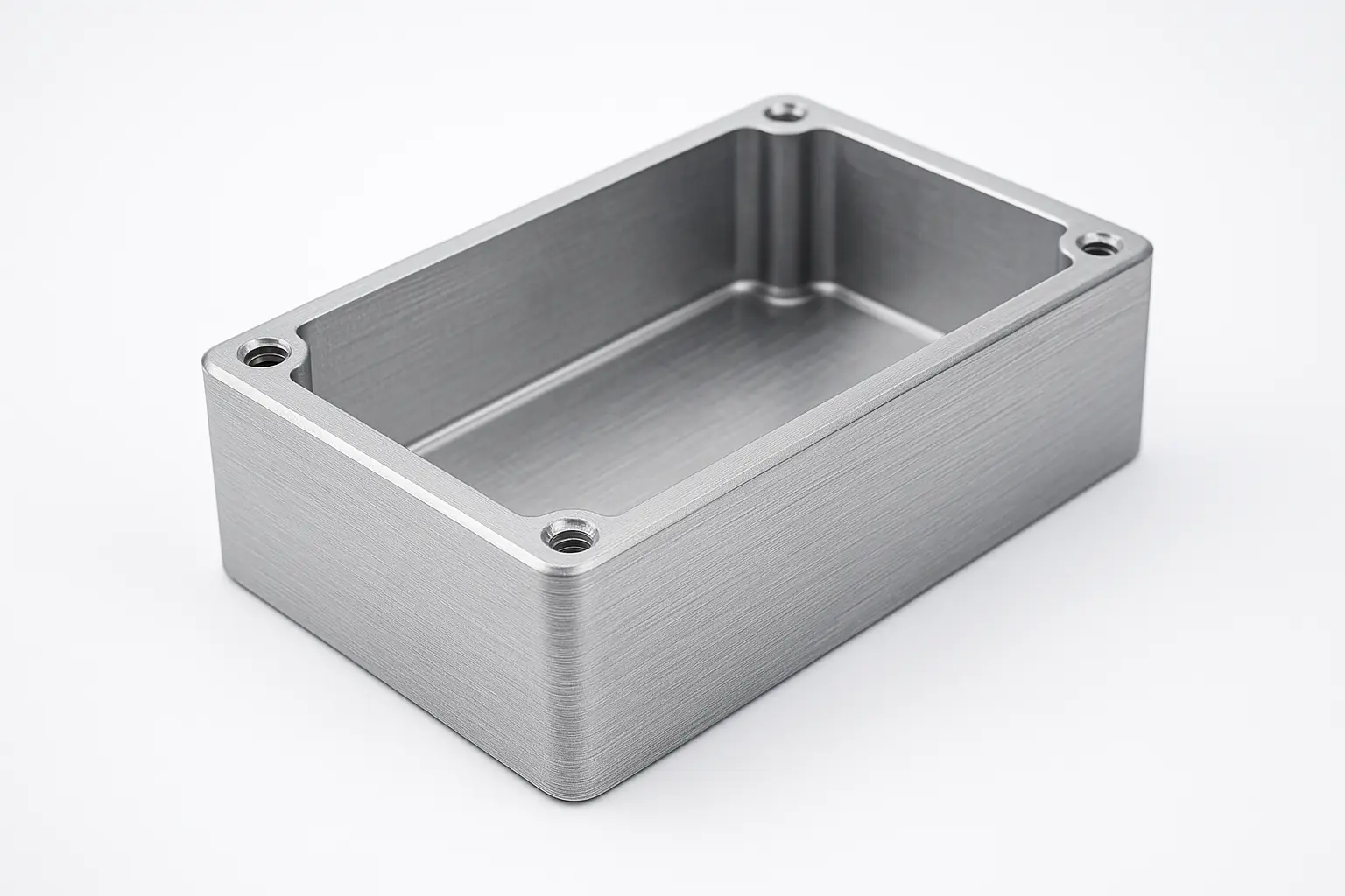
Real examples (white background)
Example 1 — pre-anodize finish
6061-T6 enclosure, finishing pass with 0.2 mm step-over on external faces. Measured Ra 0.9–1.3 µm. Light tool marks are visible in raking light; after clear anodize they would telegraph if not unified with a bead-blast.
Example 2 — bead-blast + clear anodize
Same geometry, uniform glass bead-blast then Type II clear anodize (10–15 µm). Measured Ra increases slightly, but appearance becomes uniform matte and tool marks cease to be visible at normal viewing angles.
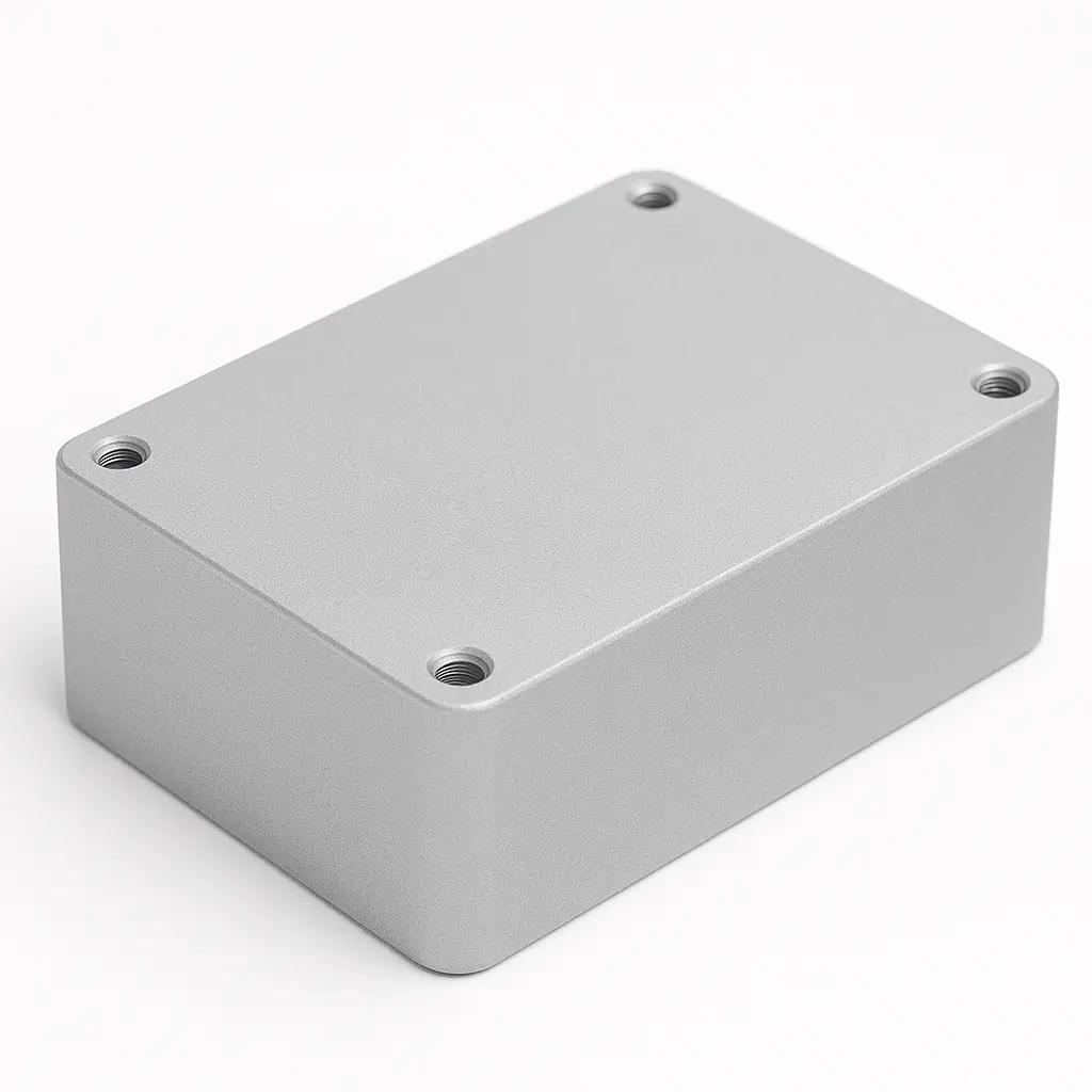
Want this look? Use the note: “Uniform bead-blast + clear anodize on external faces; pre-coat Ra ≤ 1.6 µm; critical faces A/B Ra ≤ 0.8 µm.”
FAQ — CNC milling surface finish
What Ra should I specify for visible consumer-facing parts?
A practical target is Ra 1.6 µm on the faces you can see, paired with a visual note such as “Uniform bead-blast + clear anodize.” If you need mirror-like reflections, polishing can reach ≤ 0.1 µm at a higher cost and with some risk of rounding edges.
Does anodizing make parts smoother or rougher?
Anodizing can slightly increase the measured Ra yet produces a more uniform look. Deep tool marks still show through. Always prepare the surface before coating if you want a premium cosmetic outcome.
Can I control the direction (lay) of the finish?
Yes. For sealing or sliding faces, specify lay direction relative to the axis that matters. If you don’t want visible lines, request a non-directional texture like bead-blast.
When is grinding better than a finishing pass?
Use grinding for very tight tolerances and Ra ≤ 0.4 µm on steels and sealing faces. Grinding stabilizes size and finish at the expense of added setup and process time.
How does bead-blasting affect tolerances?
It has minimal dimensional impact on most features, but do not blast tight fits and threads unless masked. The main effect is cosmetic: a uniform, non-directional matte that hides small machining lines.
What should I write in my RFQ about finish?
Specify Ra on critical faces only, add a clear visual note for cosmetic surfaces, list coating type and target thickness, and attach reference photos of your desired look. This reduces back-and-forth at inspection.
Can you measure Ra on curved 3D surfaces?
Yes, if the stylus has access and the curvature meets probe requirements. For complex shapes, we pair comparator visuals with flat coupons machined using identical parameters for correlation.
What’s the difference between Ra and Rz?
Ra is the average roughness over the sample length. Rz averages the peak-to-valley height across sampling lengths and is more sensitive to scratches. Ra is most common for general specs; Rz can catch isolated defects.
Should I specify the same Ra on every face?
No. That increases cost and cycle time with little benefit. Apply Ra to functional or visible faces and allow shop finish elsewhere.
How do coatings interact with tight tolerances?
Plan for thickness and mask critical dimensions. Hard anodize and EN add measurable thickness and may reduce clearance in bores or sliding fits. We’ll advise allowances during DFM to keep assemblies smooth.

